Arunabh_BlueStamp_Portfolio
Arunabh's portfolio for his summer robotics project
Project maintained by arunabhthakuria01 Hosted on GitHub Pages — Theme by mattgraham
Optic Hexapod
My project is a six-legged robot that can crawl, turn, move its body in place, and perform various other complex actions. It is controlled wirelessly by a remote controller which toggles its various modes. Aside from being built from acryllic parts, the hexapod also has custom 3D printed parts that allow it to safely carry its battery, and is also equipped with a camera capable of taking photos at various angles. It also has two sets of rainbow LEDs that make the robot look bright in the dark.
| Engineer | School | Area of Interest | Grade |
|---|---|---|---|
| Arunabh T | Monta Vista High School | Aerospace Engineering | Incoming Senior |
Demo Night Presentation
Modification Milestone - 7/16/2024
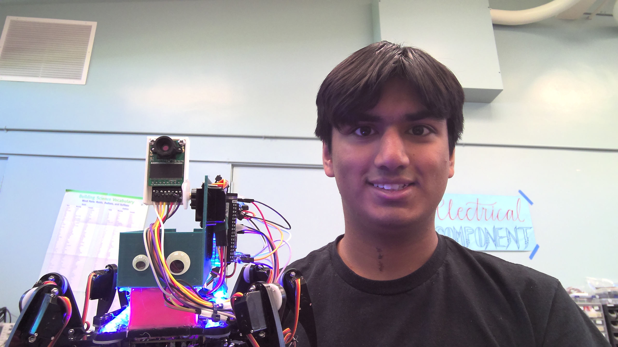
Finally, I am done with the modifications for my hexapod! My first modification was to add a camera, and have it capable of moving. The first step I took to doing this was getting a second arduino out, since the extra pins that the Robot Controller provides are not enough for the eight wires that the camera needs to operate. I also chose an Arduino MEGA to put on my hexapod since my original plan was to transfer the camera’s images via bluetooth, and it would not be possible to just use an UNO for that. Getting the camera itself to work was rather simple once I figured out the camera’s MEGA wiring, so it was then time to make the camera move.
For this part of the modification, I decided to use the spare servo that the hexapod kit came with for this, and once I had it wired, I had to figure out how to make it move in response to the controller. In order to do this, I needed to go into the robot’s .cpp files and change the code they gave me. There were several files that I needed to modify, and I needed to look through hundreds, if not, thousands of lines of code to figure out how I could add the additional servo. After three days of reading and writing code, I was able to build a command-based system for the extra servo, which you can see in the section under code. I then proceeded to modify the battery mount in order to fit the Arduino MEGA and have the servo screw in, which is pictured below.
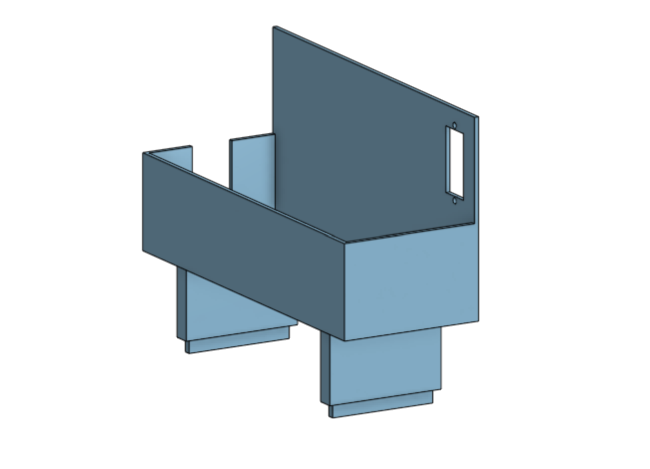
Figure 1. 3D render of the mount that the battery and the camera motor go on.
I also created a mount that allowed the camera to be screwed into the servo’s disc servo arm.
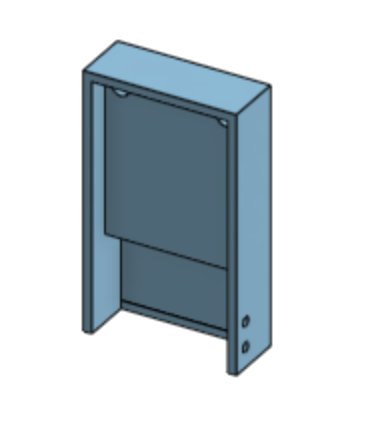
Figure 2. 3D render of the mount that the camera sits on.
After this, I put everything together and began brainstorming ideas on how to get the camera onto my computer. I realized that the Bluetooth module plan would not work out, since Bluetooth can only transfer 512B of data at a time, making it impossible to upload an entire PNG. Instead, I decdied to use an app that, whenever connected to the computer, would allow me to take photos and see them on my computer. I still had a week left at BlueStamp at this point, so I looked into another modification I could add: LED lights.
I encountered another challenge when adding these, since I actually did not have enough 5 volt pins on the Arudino MEGA to power the two strips I wanted to add. In order to solve this, I used a proto board and soldered three wires together to provide those LED strips power from just one pin. After this, I also realized that the LEDs were not getting enough power anyway since the 5 volts that came in from the Robot Controller got reduced to below 4 when going to the LEDs, so I changed the MEGA’s power supply from the controller to an additional 9 volt battery that I hot glued onto the back of the hexapod. I then coded these LEDs to go through the colors of the rainbow, which wasn’t very easy but after a few tries I got that to work properly as well.
There were many takeaways from my experience here at BlueStamp, from learning how to code in C++ and using CAD to design objects to later 3D print. However, I think the biggest thing that I learned is to approach a problem from various angles rather than just one, since that way, I will have a much better chance of figuring out a way forward. In the future, I plan on using the knowledge that I gained in Arduino IDE and CAD software to create projects for my own convenience, and I am also looking forward to using some of the skills that I gained here in my robotics team and other future ventures.
Third Milestone - 6/21/2024
My third milestone involved creating the controller for the hexapod and getting it to work with the hexapod robot. The controller consists of a board that resembles an Arduino UNO, a shield that goes on top of it with several buttons, potentiometers, switches, and a single joystick. All of these serve a function in moving the robot in some way. Depending on which buttons or switches are activated, the hexapod has different functions. For instance, if only the first switch is on, the hexapod uses the joystick’s values to crawl in different directions without rotating. However, when both the first and second swithces are turned on, the robot will crawl, with the addition of turning when sideways inputs are read. The hexapod also makes use of the potentiometers to adjust its height, and this function is on regardless of which switches have been turned on. The controller is powered by a 9V battery which is attached to the rest of a controller through an acryllic plate. It is wireless, and so it communicates with the robot through a wireless module that is on pins on top of the shield. The robot has an identical module that receives these signals and moves the robot.
I have also completed my first modification to my robot, which was adding a battery mount to the hexapod. I decided to make this because with the current situation, there was no safe space for the battery to sit on without falling off. I CADed this in Onshape, and decided to use two of the holes on the top as the places for the mount ot be inserted. While working on this, I learned that my current design for it would not work well since the legs at the bottom of my design would cause the whole 3D print to turn out badly. In order to prevent this, I made the legs a separate file and included holes in the box that the battery would sit in for the legs to insert into. After having these things 3D printed, I tested them, and luckily they fit together quite well, with the exception of the corners of the legs needing to be filed down. I still plan on changing this for the future because the legs are not long enough to allow me to put any wires onto the extra pins that the robot controller provides, and I also may change this to accomodate additional modifications. Now that my base project is completely finished, I will start modifying the robot, and the first one in mind for me is adding a camera to the hexapod.
Second Milestone - 6/18/2024
For my second milestone, I finished assembling the rest of the legs of the hexapod. I was able to accomplish this rather quickly because I had assembled the parts of all six legs while working towards getting to my first milestone. This made it so that I only needed to screw together the componenets of each leg for them to be mechanically finished. However, the wires of the 18 servos on the robot were quite messy and would touch the floor, and so I used the provided cable tidy to keep the wires together and take up less space.
After this, I calibrated the servos. This was a process where I moved each legtip to a specific spot marked on a callibration paper, and the positions of the servos were saved onto the robot controller. This ensured that every time the robot started up, it would be able to start at a fixed position. With the hexapod callibrated, I moved on to testing it with the functions in the Processing app. The robot was able to walk, turn, move up and down, and perform several other functions.
Now that I’m done with my second milestone, I will work on getting to my third. This involves getting the robot to perform all of these functions with the controller, and I also want to add a mount to the top of the robot for the battery to sit on.
First Milestone - 6/17/2024
Here is my first milestone for my main project. I chose the hexapod since it looked fairly complex as well as customizable, and it had components of mechanical, electrical, and software engineering in it. The robot is made of several acryllic parts, a robot controller that runs on Arduino code, as well as 18 servos that move the six legs of the robot. While the final project will run with a remote control, it can also move while connected to my computer with the inputs fed through the Processing application. So far, I have built the entire base of the hexapod and also created all components of the six legs. I have gotten one of these legs fully assembled onto my robot, and it fully functions with the commands on Processing.
The biggest challenge so far has been getting the leg to work with the basic code. Although I did manage to get the servos running first try, the default position seemed to face completely upwards. I tried various solutions to fix this, but nothing seemed to work. After doing a little bit of research, I found out that the servos needed to be powered while I assembled the leg, so that it could default to a position closer to what I wanted.
My plan now is to continue assembling the legs of the robot. Once they are assembled, I will callibrate the hexapod and test them with the provided code through Processing. At that point, I hope that it is able to walk and turn with no issues whatsoever.
Bill of Materials
| Part | Note | Price | Link |
|---|---|---|---|
| Hexapod | This is the main kit for the base project, containing both the robot and its controller | $126.95 | Link |
| Camera | Used to take photos from the view of the hexapod robot | $25.99 | Link |
| Servo | Outside of the hexapod, they are also used to pivot the camera | $13.27 | Link |
| Arduino Mega 2560 | This is the computer that controlls the camera and LEDs | $48.90 | Link |
| LED Strip | Purely for aesthetic purposes, it goes through the colors of the rainbow | $22.99 | Link |
| PWM Wires | These wires are used to connect the arduino to the LEDs and camera, and the robot controller to the additional servo | $6.98 | Link |
| 9 Volt Batteries | These batteries power both the arduino and the controller | $9.87 | Link |
| 7.2 Volt 3000 mAh Rechargable Battery | This is the power source for the hexapod | $52.99 | Link |
| 9 Volt Battery Connector | This connects the battery to the Arduino MEGA’s barrel jack port | $6.99 | Link |
| Googly Eyes | They sit at the front of the hexapod | $4.99 | Link |
| 3D Printer Filament | This is the material that the battery and camera mounts are made of | $35.24 | Link |
Code
Camera Pivot Code
Turn the joystick values into commands to move the camera
This snippet of code is a part of the Update() method in the FNHRRemote.cpp file. This runs only when all three switches are on, and the conditions inside this check to see if the joystick Y (vertical) value is 200 values away from the center. If so, it will add a number to the end of the fr24OutData array that tells the robot to move the camera up or down depending on the joystick’s value. If the Y value is not, then it will instead send a value that tells the hexapod to do nothing.
else{ //all 3 are on
  if(joystickYValue < 312){
    rf24OutData[rf24OutDataCounter++] = Orders::requestMoveCamUp;
  }
  else if(joystickYValue > 712){
    rf24OutData[rf24OutDataCounter++] = Orders::requestMoveCamDown;
  }
  else{
    rf24OutData[rf24OutDataCounter++] = Orders::requestEcho;
  }
}
Calls the method to move camera based on commands
This bit of code is in the UpdateBlockedOrder() method in FNHRComm.cpp. This method handles the array of orders sent to the robot, calling the methods that execute movement of the hexapod. Both conditions call the method that moves the camera, but sends a different parameter that tells the servo to spin in one direction or the other.
else if (blockedOrder == Orders::requestMoveCamUp){
  //Serial.println("Up");
  SaveRobotBootState(Robot::State::Boot);
  robotAction.MoveCam(true);
}
else if (blockedOrder == Orders::requestMoveCamDown){
  //Serial.println("Down");
  SaveRobotBootState(Robot::State::Boot);
  robotAction.MoveCam(false);
}
Code to move the servos
This snippet is inside FNHRBasic.cpp, which contains all the methods that move the hexapod. I have created this method that moves the camera’s pivot servo, either up or down depending on the parameter passed in.
boolean servoInitialized = false;
Servo pivotServo;
int servoVal;

void RobotAction::MoveCam(boolean direction){ //MOD -- Pivots Camera
	if(!servoInitialized){
		pivotServo.attach(2);
		pivotServo.write(90);
		servoInitialized = true;
		//Serial.println("Servo initialized");
	}

	if(direction && servoVal < 180){
		servoVal+=2;
	}
	else if(!direction && servoVal > 0){
		servoVal-=2;
	}
	if(servoVal > 0 && servoVal < 180){
		pivotServo.write(servoVal);
	}
}
Arduino LED Code
This is a part of the code that is on the arduino. This code makes the two sets of LEDS on the hexapod turn on, and both sets are in sync and look like a moving rainbow.
#include <FastLED.h>
#define NUM_LEDS 7
#define DATA_PIN1 10
#define DATA_PIN2 11

int r[NUM_LEDS];
int g[NUM_LEDS];
int b[NUM_LEDS];
int state[NUM_LEDS];
CRGB leds[NUM_LEDS];
CRGB leds2[NUM_LEDS];

void setup() {
 // put your setup code here, to run once:
 FastLED.addLeds<NEOPIXEL, DATA_PIN1>(leds, NUM_LEDS);
 FastLED.addLeds<NEOPIXEL, DATA_PIN2>(leds, NUM_LEDS);

 for(int i = 0; i < NUM_LEDS; i++){ //initialize LED color values
    r[i] = 255 - 15*i;
     g[i] = 15*i;
     b[i] = 0;
     state[i] = 0;
    //state values:
    //0 = red to green
    //1 = green to blue
    //2 = blue to red
 }
}

void loop() {
 for(int i = 0; i < NUM_LEDS; i++){
   if(r[i] == 255){
     state[i] = 0;
   }
   else if(g[i] == 255){
      state[i] = 1;
    }
   else if(b[i] == 255){
      state[i] = 2;
    }

   switch(state[i]){ //changes LED color based on state
      case 0:
          r[i]--;
          g[i]++;
          break;
      case 1:
          g[i]--;
          b[i]++;
          break;
      case 2:
          b[i]--;
          r[i]++;
          break;
   }
      leds[i].setRGB(r[i], g[i], b[i]);
      leds2[i].setRGB(r[i], g[i], b[i]);
 }
 FastLED.show();
 delay(10);
}
Schematics
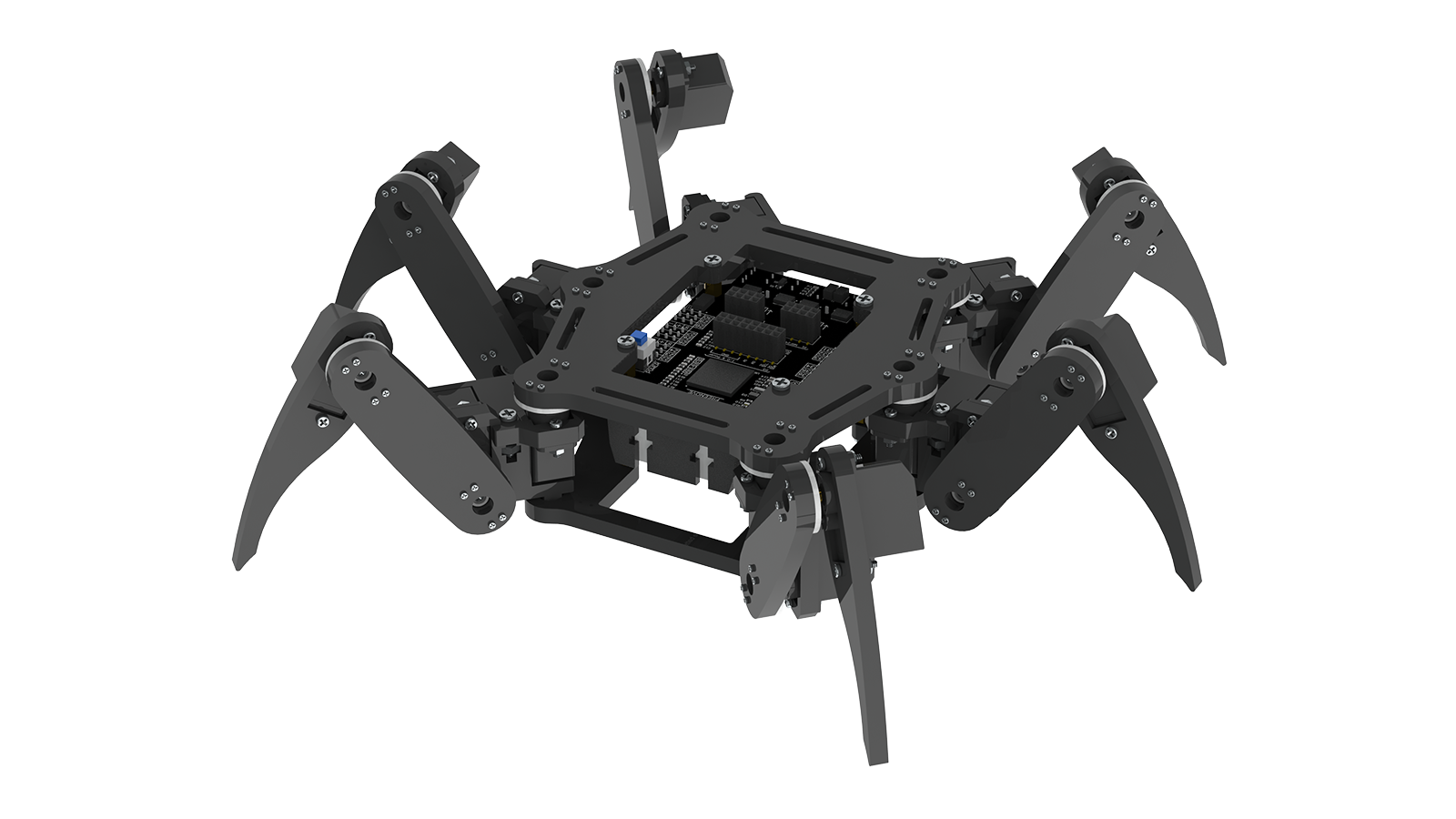
Figure 3. 3D render of the base hexapod robot’s mechanical parts without any modifications.
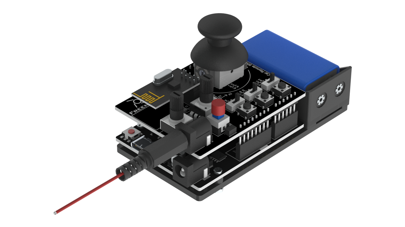
Figure 4. 3D render of the robot’s controller. This is the wireless controller that controls the robot’s movement.
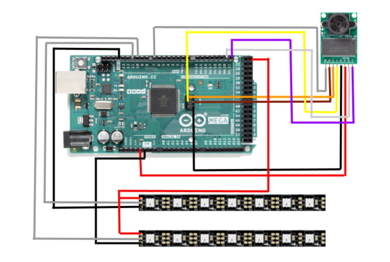
Figure 5. Wiring schematics of the camera and LEDs that are connected to the arduino MEGA.
Project Resources and Help
| Name or Source | Description and Link |
|---|---|
| Terry W. | Instructor |
| Benjamin L. | Instructor |
| Abir B. | Instructor |
| Saira B. | Instructor |
| Arduino Forums | Helped troubleshoot several errors |
| ArduCAM Github | Provided all code as well as the app needed for the camera |
| Freenove Hexapod Github | Provided all the code and instructions for the Hexapod |
Starter Project: Arduino - 6/12/2024
Here is my starter project. It is an arduino board with a proto shield on top of it as well as a breadboard on the side. This proto shield allows me to wire several components on top of the arduino. I also used a breadboard to wire a button to the arduino. I have wired two LEDs onto the proto shield, and they are both controlled by the button. I coded them such that the red LED only turns on while the button is pressed, and the green LED is turned on and off whenever the button gets pressed.
One of the biggest challenges I faced was with getting the button to work. I originally wanted to have the button soldered onto the proto shield, but after testing code with this setup, I found out that it was not a stable input source. After doing a little bit of research into wiring buttons, I learned that I needed a constant power source and resistor at the ground source, and so I made the decision to switch to wiring the button on my breadboard instead.
My starter taught me several basics of arduino code, such as how to initalize inputs and outputs, and I also learned how to use a breadboard. It also helped me refine my soldering skills, and I have become much more precise with soldering smaller wires together.
Starter Bill of Materials
| Part | Note | Price | Link |
|---|---|---|---|
| Arduino UNO | Computer that runs the code and provides power to all components | $15.19 | Link |
| Breadboard | Allows for free wiring of buttons, sensors, and other components | $6.75 | Link |
| Proto Shield for Arduino | Allows for soldering of several components, and also provides custom space for buttons, LEDs, and capacitors that come with the shield. It also has extensions of several arduino ports. | $9.95 | Link |
Starter Code
int buttonPin = 13;
int redLedPin = 8;
int greenLedPin = 9;
int buttonState = 0;
int buttonStore = 0;
int pressed = 0;

void setup() {
  pinMode(redLedPin, OUTPUT);
  pinMode(greenLedPin, OUTPUT);
  pinMode(buttonPin, INPUT);
}

void loop() {
  buttonState = digitalRead(buttonPin);
  if(buttonState == HIGH){
    digitalWrite(redLedPin, HIGH);
    if(pressed == 0){
      pressed = 1;
      if(buttonStore == 0){
        buttonStore = 1;
      }
      else{
        buttonStore = 0;
      }
    }
  }
  else{
    digitalWrite(redLedPin, LOW);
    if(pressed == 1){
      pressed = 0;
      if(buttonStore == 0){
        digitalWrite(greenLedPin, LOW);
      }
      else{
        digitalWrite(greenLedPin, HIGH);
      }
    }
  }
}
Starter Schematics
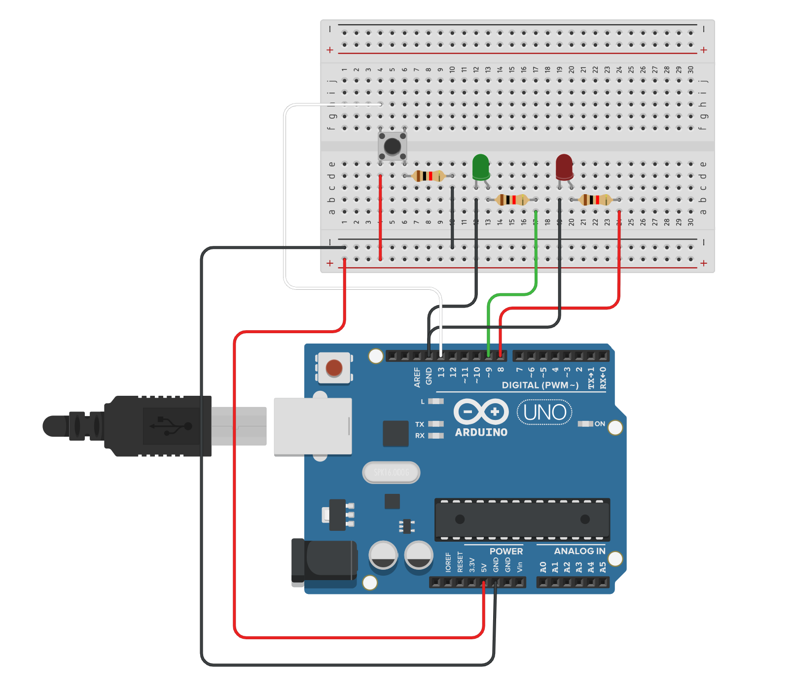
Figure 6. Wiring diagram of the aruduino’s LEDs and buttons. Although the LEDs are actually mounted on top of the proto shield, they are on the breadboard instead to show the wired connections in the circuitry.